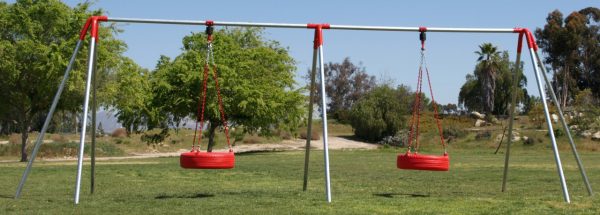
This heavy-duty in-ground swing set is designed to be durable and safe for commercial use. It includes two bays, each capable of holding up to two children aged 12 and under, in accordance with the guidelines set by ASTM and CPSC. The set is suitable for in-ground installation, with a height of 6 feet and two Tire Swing Assemblies. Colors for the End Frame Fittings and Tire Swings can be specified to match your preferences.
Please note that the actual weight limit of the set depends on various factors such as installation method, soil type, amount of concrete used, frequency of use, and other external factors. Therefore, we do not provide a specific weight limit for our swing sets. However, if installed according to our instructions, the set should exceed the safety requirements set by ASTM and CPSC. This product is built to last up to 5 years in optimal conditions and up to 2 years in harsh conditions, although replacement may be necessary in some circumstances.
TOOLS AND PARTS NEEDED:
Ladder, ¾” wrench, Ratchet socket wrench, Tape measure, A5750 supplied Allen wrench for shackles, and 6mm Allen wrench for set screws. Stakes for marking holes. Shovel, Bricks, Gravel, Wheelbarrow for mixing concrete, Water, Concrete, Trowel, Level, Warning signs. Protective surfacing according to ASTM F1292 for a fall height of 6’.
PARTS INCLUDED ARE:
A3000 – 2 green or red A7700 – 6 blue, green, red or yellow
A3025 – 1 green or red Pipe Legs A – B – 8’ – 4
A5200 – 2 Pipe Middle End Legs AA – 8’ – 2
A5730 – 12 Pipe Middle Legs C – D – 8 – 2
A5750 – 1 Top Rail 14’ – 2
A5600 – 2 black, blue, green, red or yellow
MEASUREMENTS FOR SWING FRAME:
The Front (A) and Back (B) legs are 74” apart above ground and 92” below ground. Lengthwise, the two front legs (A) to (A) are 247” apart. The two middle legs (AA), which are the legs furthest apart, are 305” apart. The front leg (A) to the middle leg (AA) is 47” apart above ground. The height of the set is 6’.
**INSTALLATION, SAFE USE & MAINTENANCE INSTRUCTIONS**
IMPORTANT: To keep children safe from harm, follow these precautions and instructions when installing, using, or maintaining this playground equipment. You can also call us at 1-800-433-2573 for more information or see http://www.cpsc.gov/cpscpub/pubs/324.pdf.
Installation: Read all instructions before attempting assembly. The minimum of clearance between the bottom of the tire and the protective surface should not be less than 12”. The minimum clearance between the seating surface of a tire swing and the legs of the frame should be 30” when the tire is in a position closest to the legs. The proper use zones needed for a public tire swing set should extend in any direction from a point directly beneath the pivot point for a minimum distance of six feet plus the length of the suspended unit. The use zone should never overlap the use zone of any other equipment. For residential sets see spacing dimensions on Page 4 of the Outdoor Home Playground Safety Handbook. Only one tire swing is allowed per bay. No other type of swing is allowed in bay. Install swing set where a child can easily be supervised. Do not install playground equipment over concrete, asphalt, or any other hard surface. A fall onto a hard surface can result in serious injury to the equipment user. Grass and dirt are not considered protective surfacing because wear and environmental factors can reduce their shock absorbing effectiveness. Carpeting and thin mats are generally not adequate protective surfacing. Install your play equipment on level ground with adequate surfacing and anchoring. Use proper hardware, and tighten all connections.
Lay out all the pipes and end frame fittings on the ground about two feet from where you have determined you want to place your swing set. Do not dig holes until frame is assembled, as there may be some variance in leg spacing. Lay an end frame fitting on one end, then a top beam, then a middle frame fitting, and finally the remaining end frame fitting.
Slide the one end frame fittings on the end of a 14’ top pole with the three legs of the end frame fittings, pointing down. Slide the middle frame fitting on the other end of the 14’ top pole with the two legs pointing down. You may have to force pipe into pipe opening. Tighten the included set screws on the top of the end frame fitting and the middle frame fitting, using the 6mm Allen wrench.
Insert the remaining 14’ top beam into the other end of the middle frame fitting. Slide the remaining end frame fitting on to the other end of the 14’ top pole with the three legs pointing down. . You may have to force pipe into pipe opening. Tighten the included set screws on the top of the end frame fitting and the middle frame fitting, using the 6mm Allen wrench.
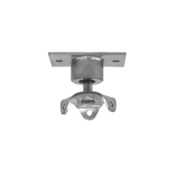
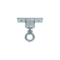
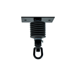
Put each half of a tire swivel around the first 14’ top beam at the midpoint of the top beam. With the head of one of the included bolts, starting on the top of the pipe and going down towards ground, put bolt through bolt holes in both the top and then bottom half of tire swivel plates. Put flat washer on bottom of bolt, and secure with the included nylock nut. (Bolt, washers and nuts are included.) Put bolts and washers through beam so that nuts are on the bottom of top beam, and so that the bolt is attached with no more than two thread showing beyond the nut. This will prevent a protrusion on the top beam. Check to see bolts are straight and nuts are tight. Repeat this process with all four bolts.
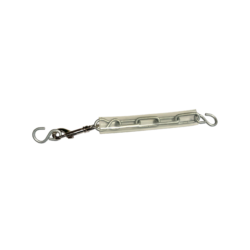
Then, attach H shackles from the chain to the swivel. The shackle should not crimp material producing a wear spot on whatever material you are attaching to shackle. Unscrew both shackle bolts from one side of shackle body with A5750 wrench. Place bolt through chain and tire swivel eye. The longer side of the h shackle goes through the round eye on the bottom of the tire swivel. The short side goes through the chain. Screw both shackle bolts back into shackle body. Shackles should never be pulled at an angle because the capacity will be tremendously reduced. Centralize whatever is being attached on the bolt with suitable washers or spacers. Ensure the bolt is correctly screwed into the shackle eye with an A5750 wrench. Check that the threads are fully engaged with the body, but not so tight that it causes the body to bend in or that the threads go past the body by more than two threads. Repeat this process with all three chains.
You can now attach tire to the bottom of the chain with H-shackles. The shackle should not crimp material producing a wear spot on whatever material you are attaching to shackle. Unscrew both shackle bolts from one side of shackle body with A5750 wrench. Place bolt through chain and built in tire eye bolts. The longer side of the h shackle goes through the tire eye bolt. The short side goes through the chain. Screw both shackle bolts back into shackle body. Shackles should never be pulled at an angle because the capacity will be tremendously reduced. Centralize whatever is being attached on the bolt with suitable washers or spacers. Ensure the bolt is correctly screwed into the shackle eye with an A5750 wrench. Check that the threads are fully engaged with the body, but not so tight that it causes the body to bend in or that the threads go past the body by more than two threads. Repeat this process with all three chains. Make sure all lengths of swing chain are equal, so the tire hangs evenly.
Attach the second tire swivel, chains and tire to the second 10’ top beam using the same process as described above.
After attaching the second tire to the chains, you are now ready to assemble the frame. Slide the frame leg poles into each leg of the end frame fittings. The two pipes that are 97” insert into the middle leg of the end frame fittings, and the four pipes that are 99” go into the two legs openings that are on either side of the middle leg. Insert two pipes that are 99” long go into the two Middle Frame Fitting leg openings. Tighten the included set screws for each leg. The set screws use a 6 millimeter Allen wrench. Make sure set screws are tight. Make sure that pipes are all far enough in frame fittings holes to stabilize frame. After frame is all assembled, have multiple people lift structure and rotate structure, so that it is upright.
Measure distances between legs, then, drive stakes into the ground at the correct distances for each pipe at the location of the swing set as you have determined above. Dig holes until you have the correct number of holes. Dig holes that are two feet deep and two feet in diameter.
Place a brick in the bottom of each hole with the widest edge facing up. The bricks will prevent the swing set from sinking in the dirt. Set the swing set in place. Lift the set and do not drag. Make sure there is at least four inches of space around the entire end of pipe, so that concrete will surround the pipe. Hold a level on the top bar of the swing set. Add gravel under each brick to adjust the height as needed.
Pour the contents of two 80-lb. bag of concrete into the wheelbarrow. Add the recommended amount of water to the concrete, and mix with the shovel until there is no dry material. Shovel the mixed concrete into a hole. Smooth the concrete with a trowel. Add dirt if necessary to fill hole, leaving enough space for surfacing. Repeat this step for each hole. Allow the concrete to dry for twenty-four hours, and check for sturdiness before allowing children to use swing set. Try swinging tire without child in it first to make sure everything is working correctly before allowing children to get in tire swing..
Before allowing children to use set, install adequate surfacing under swing sets to prevent injury from falls. Protective surfacing that meets ASTM F1292 must be installed under swing set and extends at least six feet from the sides of the set and twice the height of the top bar in the front and back of swing set. Protective surfacing is one of the most important things that you can do to reduce the likelihood of serious injuries.
The new CPSC standard states the owner/operator of the swing set needs to post warning signs outside the use zone that are readily visible to the intended viewer and alert them to the potential hazard in time to take appropriate action. This message may be on either a sign or label outside the use zone. Signs should be posted that state the appropriate age group for the swing set. Not for Adults. Adults should supervise children at all times. Do not allow children to stand on or use unsafely. Do not allow set to be used if damaged. Remove helmets, drawstrings or accessories around the neck which are all known to create head entrapment or entanglement hazards. Where applicable, Hot play surfaces are known to reach temperatures high enough to cause serious burns to children generally less than 4 years of age.
Specifications for all warning signs or labels should conform to ANSI Z535.1 and ANSI Z535.1 or ANSI Z535.1 in the following areas: legibility, type of lettering, clarity of message and symbol, color specifications and work message and visibility. The labels or signs should be durable and conform to UL 969. It has been and continues to be the responsibility of the owner/operator to replace signs or labels or both should they become illegible, destroyed or removed. Signs can be purchased at http://www.mindspring.com/~safetyplay/
Safe Use:Each tire swing is intended for no more than three children, 4 – 12 years old. Not for Adults. Adults should supervise children at all times. Do not allow children to stand or kneel on tires or use unsafely. Do not allow swings to be used if damaged. Do not use if wet. Instruct children not to wrap chains around top beam. Tell children to watch for children and adults standing, walking or running close to moving swings and to stop swinging to avoid hitting them and causing injury. Tell children to hold chains tightly in each hand while swinging. Tell children not to get off swing until it has stopped completely.
Maintenance: At beginning and end of each play season and once a month during play season, check for sharp edges on hardware and/or cracks in tire or other accessories. Check that set screws are tight on frame fittings. Check that frame is sturdy and does not rock from side to side or rock to or fro. Make sure concrete is still secure and that footing surface is not a tripping hazard. Check for rusty or worn chain. Check to make sure shackles are closed properly and not worn. If worn and shackles require replacing, make sure that proper hardware is used to replace worn h-shackles. WARNING: THIS SWING REQUIRES EITHER A LARGE END S-HOOK OR AN H-SHACKLE TO CONNECT TIRE TO CHAIN. NOT USING NAMED FASTENERS CAN RESULT IN TIRE BREAKING AND CHILD BEING INJURED. Check to make sure all lock nuts are tight. Check that screws are secure. Carefully check hole around built in eye bolts to look for wear.
Pay particular attention to the maintenance of the tire swivels. The likelihood of failure is higher for tire swings due to the added stress of rotational movement and multiple occupants. Check spinning action and make sure there is no binding. Using a grease gun put a sufficient amount of standard grease into the swivel through the grease fittings. This is very important to reduce wear and prevent injury. A tire swivel without grease will wear very quickly. This can cause failure of swivel, which can result in severe injuries. When putting grease in swivel, you will see the grease come out of grease fitting when it is full. Wipe off excessive grease. We have used a McKay Molybdenum Disulfide grease cartridge, but any standard grease cartridge from any auto part store should be sufficient. There are two grease fittings that must be checked and filled with grease during maintenance. The first is at the bottom of the hanger in the swivel head and is easily seen and reached. The other grease fitting is harder to reach, and is located under the rubber boot on the universal joint. However, it is important that this grease fitting be checked also. To do this: Cut the zip tie holding the rubber boot. Take two flat head screw drivers and lift the boot down, so that you can put the grease gun nozzle on the grease fitting. Put in sufficient grease. Raise up the rubber boot and secure with another zip tie. Cut off excess plastic tail on zip tie. Make sure all nuts and bolts are secure and not worn. Look for loose parts, torn or missing rubber boots, cracks in metal or rust. Please, check for vandalism. Check for rust. Take a wire brush or piece of steel wool and scrub rust from metal surfaces. Replace parts necessary for safety. Checkresilient surfacing for appropriate depth and cleanliness. Maintaining adequate surfacing is extremely important in reducing injuries. Maintain detailed inspection and maintenance records for public-use playground equipment.
Any damage from vandalism, abuse or misuse VOIDS all warranties.
BASIC POLICY & PROVISIONS
Playset’s are shipped via Curbside Shipping. Delivery will be done by a tractor/trailer (a semi truck). The driver is only responsible for delivering (driving) the order to your curb. A delivery appointment is scheduled by the freight company via the phone number (s) you provide in your order. No delivery will be made unless an appointment is set. The delivery person requires your assistance in unloading the order. Any additional services, such as two-man delivery or inside delivery are not included in the price of the freighted item. The cost of these additional services varies from city to city. They usually cost between $50.00 and $150.00 extra. You may purchase the additional services directly from the freight carrier when delivery is scheduled. It is a good idea when you make your appointment, to have the freight company call you 30 to 45 minutes before delivery so as to avoid having to wait for the driver to show up.
RECEIPT OF SHIPMENT/CUSTOMER RESPONSIBILITY
Before signing for you order, check to see that you are receiving the same number of cartons, bundles, and loose pieces etc., indicated on your receipt. Note any shortages or visible damage on your receipt and have the driver note these also.
Damage which is found after you unpack the shipment (concealed damage) must be reported to Customer Service immediately. Please closely inspect your shipment! Most freight companies allow 10 days from receipt to report concealed damage.
NOTE: If you discover damage of any kind, DO NOT DESTROY ANY ORIGINAL SHIPPING CARTONS.
LOSS OR DAMAGE IN SHIPMENT
Customer signing bill of lading at time of delivery is our receipt from the carrier. We therefore, are released of all responsibility for loss or damage in transit. Merchandise, as received by you, should be carefully checked against the freight bill to be sure delivery of all items has been made.
Count the shipment and inspect for damage. If shipment is not delivered to you in good order and in accordance with the quantity shown on the Freight Bill of Lading, please not the shortage or damage on the Freight Bill before you sign for the shipment. Please contact your sales representative to advise the company of the shortage or damage.
As soon as possible after delivery, open all cartons and inspect for concealed damage. If you do have shortages or damage in cartons, please contact your representative’s office immediately so replacements can be made.
Do not throw away your copy of the Freight Bill. Any damaged or missing pieces not signed for as such on the Freight Bill of Lading will be replaced at the replacement cost, and freight charges will be charged to deliver the merchandise to your site.
Please note that the driver is obligated to bring your merchandise to the end of the trailer. It may then be advisable to have someone on hand to assist in unloading the merchandise as these systems come on 8’ to 12’long pallets and weigh a minimum of 500 pounds.
SKU#H6T2

